Arduino Summative Assesment (SELC POE)
Define the Problem
3D printing enclosures are not usually actively heated with a dedicated heating element, rather, rely on the heat dissipated from the 3D printer itself. As a result, prints may result in uneven warping due to a variation in chamber temperature.
Generate Concepts
To solve this problem, I generated a few ideas:
- Thermistor / Temperature sensor for chamber temps
- LEDs / Colored LEDs for indication
- LCD Screen for precise measurements
- Buzzer for alarms / critical temp warnings
- Ultrasonic Sensor for Wake on Presence
- PIR sensor for Wake on Presence
Develop a Solution

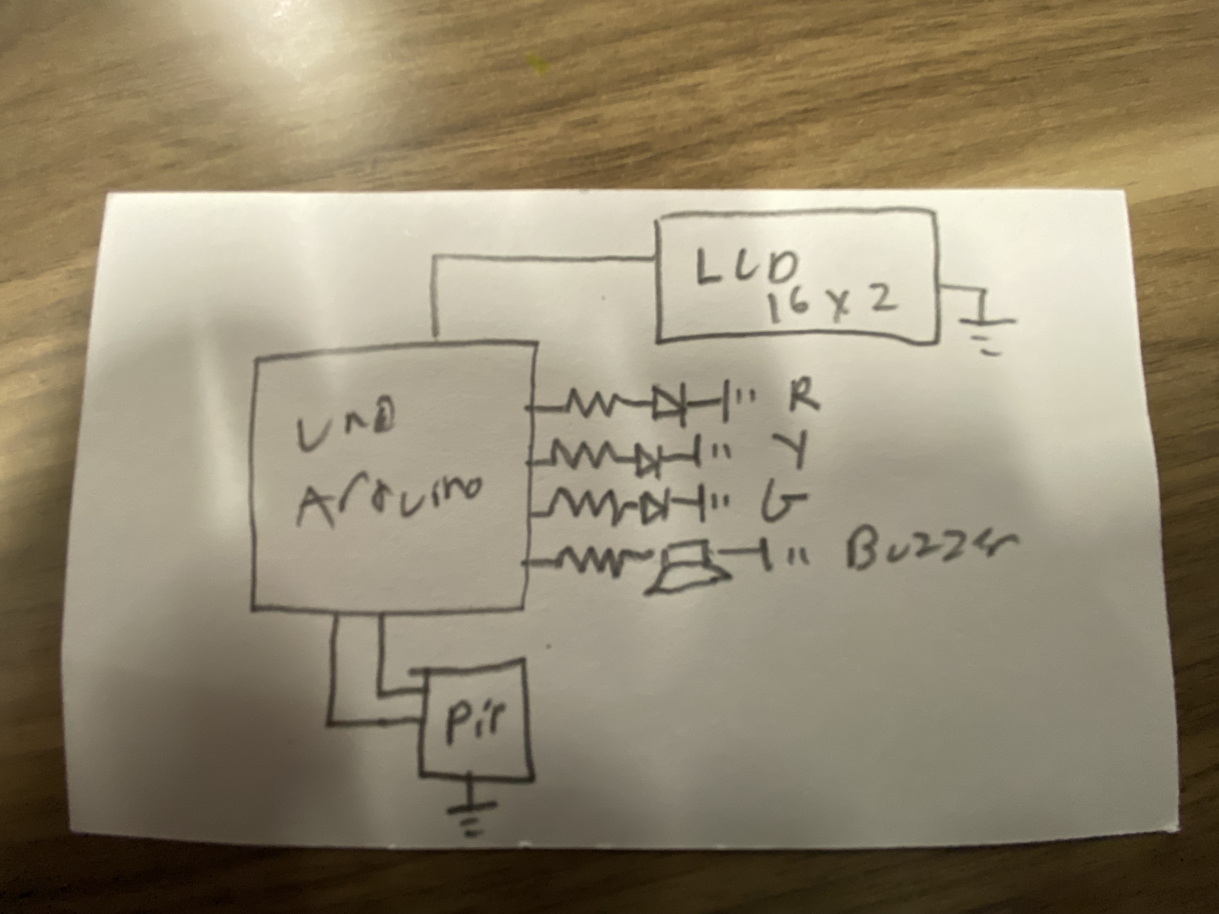
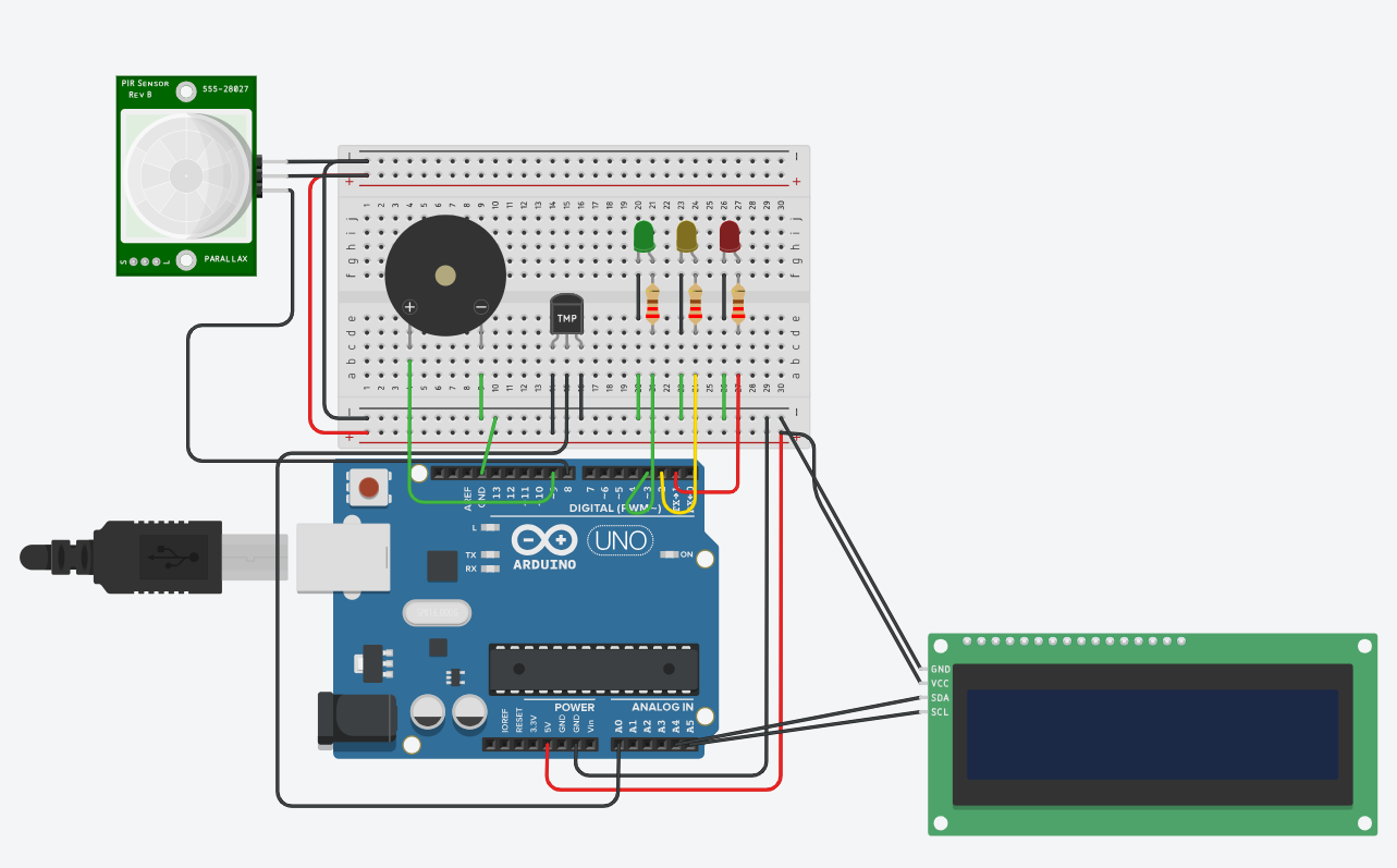
For my solution, I utilized a Red, Yellow and Green LED, a buzzer, PIR sensor and a 16x2 LCD display (i2C). The LEDs and buzzer both integrate with eachother, as Yellow indicates a normal temperature, Green indicates an optimal temperature, and Red indicates a non-ideal temperature, along with the buzzer activating when the Red LED is illuminated. With the PIR sensor and LCD display, the PIR sensor acts as a wake-on-presence sensor, with the LCD screen activating and displaying the accurate temperature when the sensor is activated.
Construct and Test a Prototype
Here is what the finished prototype looks like:

And here is my code:
#include <Adafruit_LiquidCrystal.h>

/*
Kendrick Lee - Chamber Temp for 3D Printing
SELC POE 2024
*/

Adafruit_LiquidCrystal lcd_1(0);

void setup()
{
pinMode(8, INPUT);
  pinMode(3, OUTPUT);
  pinMode(2, OUTPUT);
  pinMode(1, OUTPUT);
  pinMode(9, OUTPUT);
  // LCD Inits
  lcd_1.begin(16,2);

}

void loop()
{
  digitalWrite(0, LOW);

  // Parse Temps
  int tempReading = analogRead(0);
  float voltage = tempReading * 5.0;
  bool pirVal;

  voltage /= 1024.0;

  // Temp in Celc
  float tempCelc = (voltage - 0.5) * 100;

  // PIR Sensor
  pirVal = digitalRead(8);

  // LCD Parsing
  lcd_1.setCursor(0, 0);
  lcd_1.print("Temp (*c)");

  lcd_1.setCursor(0, 1);
  lcd_1.print(tempCelc);

  // Behavior Stuff
  if (pirVal){
  	lcd_1.display();
  }
  else {
  	lcd_1.noDisplay();
  }

  if(tempCelc >= 68){
  	digitalWrite(3, HIGH);
    digitalWrite(2, LOW);
    digitalWrite(1, LOW);
    digitalWrite(9, LOW);
  }
  if (tempCelc > 15){
  	digitalWrite(2, HIGH);
    digitalWrite(3, LOW);
    digitalWrite(1, LOW);
    digitalWrite(9, LOW);
  }
  else{
  	digitalWrite(1, HIGH);
    digitalWrite(2, LOW);
    digitalWrite(3, LOW);
    digitalWrite(9, HIGH);
  }
}
(arduino C++)
Evaluate Solution
Overall, I think that my solution works fairly well, minus the latency and lag generated by the TinkerCAD simulation, which isn't a problem in real life. However, one addition I would make would be a method of communication between the Arduino and main-board of the 3D Printer, so that heating / cooling the chamber doesn't mean leaving a heating element on 24/7. This could probably be done through a communication protocol such as SPI or i2C.
Present Solution
Here is a video detailing what this project is: